Haha whoops, I'm not dead I swear. On the plus side, I've been pretty productive - I've already completed not one but three P2K FA2 DCC installs, never mind other projects too. I'm reasonably happy with the results, and the method is general enough that it could be experimented on in the future.
But, let's not get ahead of ourselves. It's important to make sure that the mechanics and electrics of a loco are in good shape first, and when we last left NYC 1050 it needed some work. Besides the split gear issue, the past 30 years have not been kind to the factory-applied grease, so we'll need to open up the trucks to clean that gunk all out.
 |
| Spoiler: It's gross |
Both ends of the loco work about the same, so I'll describe the procedure once (but keep in mind you'll be doing it twice). First, do yourself a favor and remove the two screws holding either the fan assembly or the cab assembly to the frame. This isn't strictly necessary, but will make putting the drive back together later much easier. (Ask me how I know...)

The fan platform will pop right off. The cab platform has some wires running through it, so if you're doing a DCC install now is a good time to think about disconnecting those (which I'll discuss more in the next part).
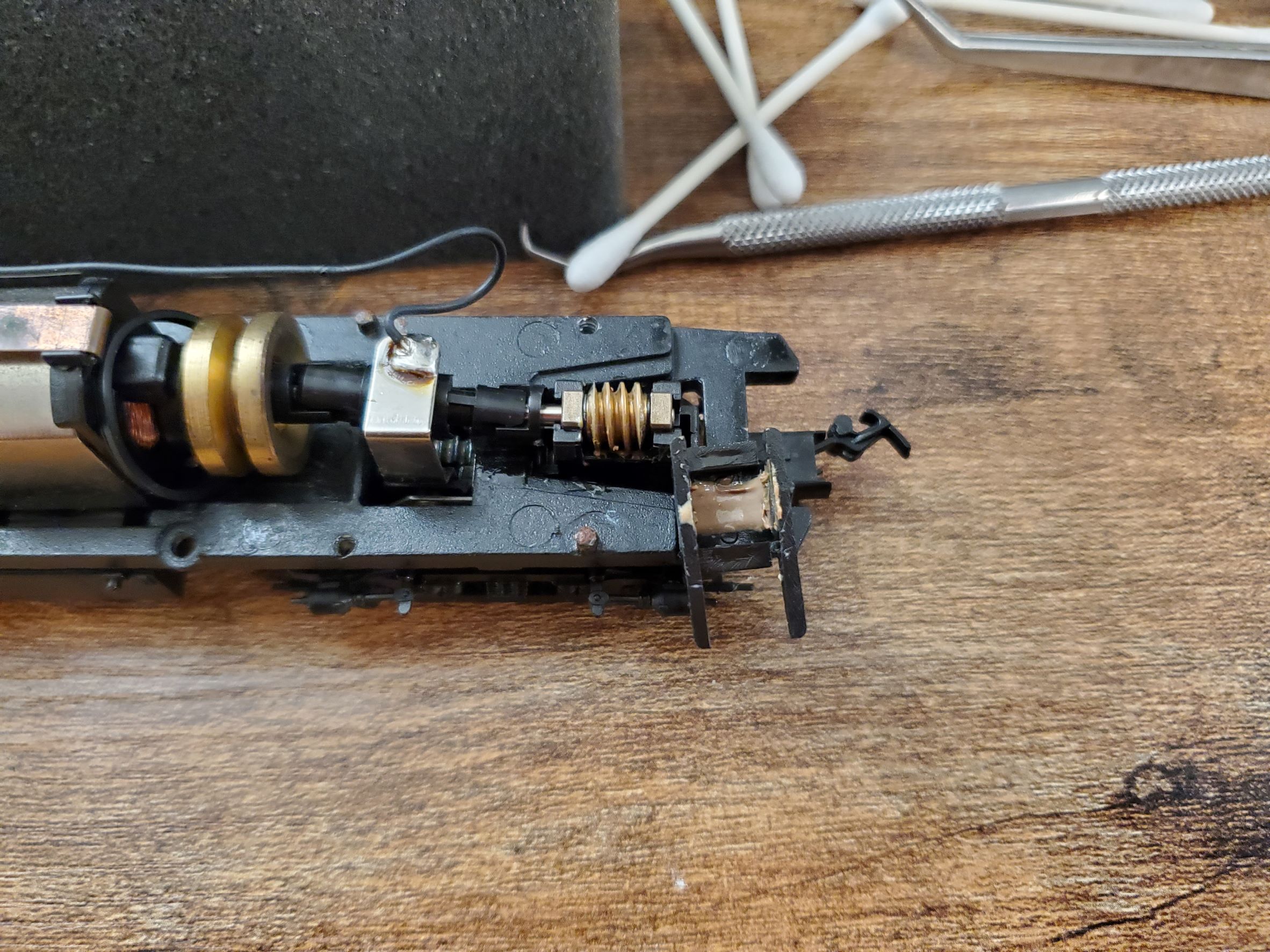
Once the platform is removed, use a flat tool to pop off the worm gear cover. Keep in mind that the worm gear cover also holds the truck onto the frame, so that will be loose - or if the wire is disconnected, completely free.
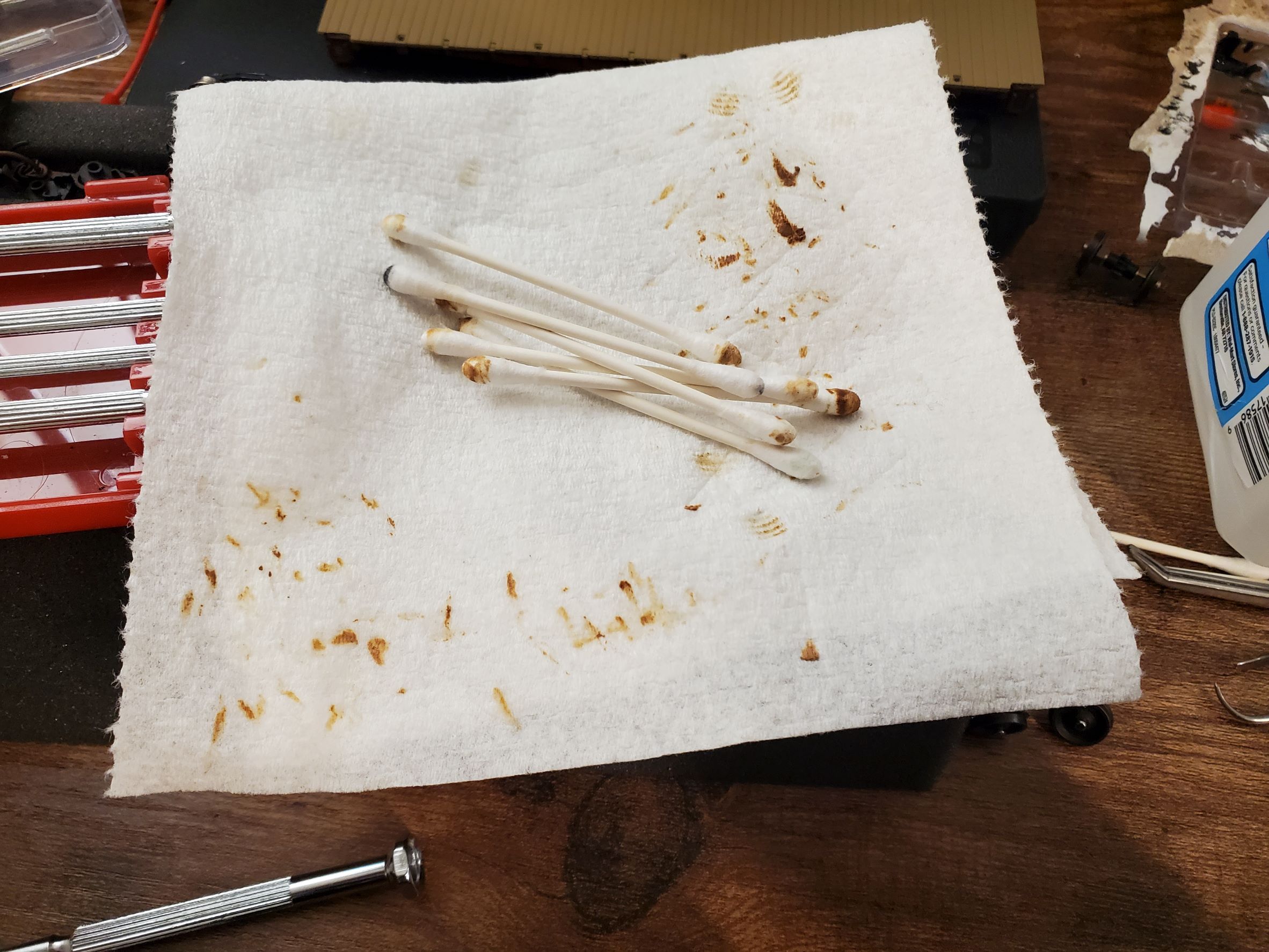
 |
| Directional continuity is for the weak |
See that peanut-butter-looking junk on the inside of the worm gear cover? That was grease at one point, and the whole idea behind this disassembly I'm doing is to clean that out.
While the worm cover is off, carefully lift up the worm gear (its bearings will come with it) and pull the worm gear assembly off of the drive shaft from the motor. This should take no effort; if it does then you're doing something wrong.
Flip the engine over (resting it on its weight helps), then the truck covers may be removed by gently spreading the four tabs just inside of the axles. I like to use a hook tool to access these tabs around the axles, but you could probably make do with a thin flat-head screwdriver, or the back of a hobby knife.

At this point, you should have access to all of the gears in the truck. What you'll want to do is remove the old grease and junk. It doesn't have to be perfect, but make sure to get in between the teeth of the gears (a pointy tool to scrape the grease out is helpful). Don't forget the worm gear too. If you're replacing the drive axles with new Walthers parts, that saves you two gears worth of cleaning.
Assembly is largely the reverse of disassembly. Place the new drive axles in to the truck, making sure that the bearings on the axles seat squarely into the slots in the sideframes. Lube the gears lightly, then pop the lower truck cover back on. On the top of the truck, slide the worm gear back onto the motor shaft - notice that the shaft is keyed, and so will need to be aligned correctly to fit on. Make sure that the worm gear bearings seat squarely into the slots on the top of the truck, apply a little lube, then make sure that the truck is seated on the pin underneath the frame before popping the worm gear cover back on.
By the time you've done three of these engines - hence 6 trucks in all - you'll be able to do this in your sleep.
If you'd like to convert your loco to use Kadee couplers, Kadee offers a handy dandy set of instructions...which are mostly correct. I take issue with the following:
- Rear: Use a short-length #33 coupler instead of the suggested medium-length #38 coupler. (Or #33 for both couplers on an FB2.) The suggested #38 coupler leaves a large gap between diaphragms when coupling multiple units together. Even with the #33 coupler leaves a slight gap, but it's an improvement. Given the size of the gap, I can't imagine that you would have any issues using a short coupler, unless maybe you have 15" curves on your layout or something.
- Front: The suggested long-length #36 coupler works if you drill and tap the rearward mounting hole . If you tap the forward mounting hole, you'll want a medium-length #38 coupler. Having done it both ways, it looks indistinguishable which is which once you put the shell on. Pick which one makes you happy, and/or whatever you have the parts handy for.
Other than that, the procedure as-given works just fine. Drill, tap, coupler. Bam.
 |
| It should look like this when you're done. |
At this point, you should finyanly have a locomotive which is ready to have DCC installed in it. Which...will be the subject of the next part of this series. Maybe I'll even have that post done this month! Who's to say.


No comments:
Post a Comment